App Dev · · 4 min read
NetLay: Diagrams on demand and tracing a path
Three exportable pictures generated from one data model, no diagramming library involved, and a troubleshooting tool that fell out of the port bookkeeping almost for free.
A picture you can put in a document#
Here is the note that started this one.
"I want to have a feature where we can export the map into different images like this for one (im not sure what you would call this)"
What was attached was a diagram of devices grouped by VLAN, the kind of thing you end up making by hand in Visio at four in the afternoon when somebody has asked for the network on a page.
The thing is, NetLay already knows all of that. It knows every device, every port, every uplink and which VLAN each one is in. If the data is already there then a diagram is not a drawing job, it is a layout job, and a layout job is just code.
So there are three exports now, all generated from the same model.
The first is the physical map exactly as you see it. It clones the live drawing, drops the moving pulses and anything you had selected, inlines the building images, and renders it to a PNG at twice the size so it still looks sharp in a document.
The second is a connection diagram. Switches are placed in columns according to how far they are from the core, or from the most connected switch if nobody has said which one is the core, with their uplinks curved between them and labelled with the ports and the cable type, and the devices hanging underneath. No graph library. Working out which column a switch goes in is a few lines once you know the uplinks, and after that it is arithmetic.
The third is the one that was asked for. A box per VLAN, the members inside it, and where each one is plugged in.
They are generated as SVG with a preview first, and you can take the SVG or a PNG. SVG because the text stays text, which means it is searchable in the document you paste it into and it does not go fuzzy when somebody prints it at A3.
Tracing a path.#
The other feature in this build took an afternoon because six weeks of port bookkeeping had already done the hard part.
Select one thing, shift click another, and the app works out how the traffic physically gets from one to the other. It is a breadth first search over a small graph where a device joins its switch through its port, a virtual machine joins its host, and switches join each other over uplinks and stack cables. The route lights up in cyan, everything else dims, and the inspector lists the hops with the port or cable used at each step.
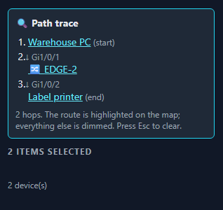
That is the obvious use. The more useful one turned out to be the failure case.
When it says there is no wired route between two devices, that is almost never true of the building. It is true of the documentation. Something is missing, usually an uplink nobody recorded or a device whose port was never filled in, and the trace is the quickest way I have found of flushing those out. Point it at two things you know are connected, and if it cannot find them a path then you have just located a gap in your own map.
Cabinets count as nodes in the graph as well, so you can trace from a rack rather than having to pick something plugged into it. The highlight survives the data refreshing underneath it, and Escape clears it.
What this build taught me#
Both halves of this post come from the same place, which is that the boring work pays later.
Nobody enjoyed modelling port modules. It was three evenings of bookkeeping with nothing to show at the end except port names that were slightly more correct. But the export diagrams and the path trace are both only possible because the model knows what is plugged into what, at the port, rather than knowing that a printer is vaguely associated with a switch. Neither feature needed any new data. They are both just questions asked of something that was already written down properly.
The flip side is that I now have a connection diagram I am not completely happy with, because placing switches in columns is fine for four of them and starts to look like spaghetti at fifteen. That one gets rebuilt later in the series.
Next time, giving the map a memory, so it can answer the question it currently cannot, which is whether that thing was down last night.